How I built a Pen Plotter
Materials
For a comprehensive list of parts I used, refer to parts list.
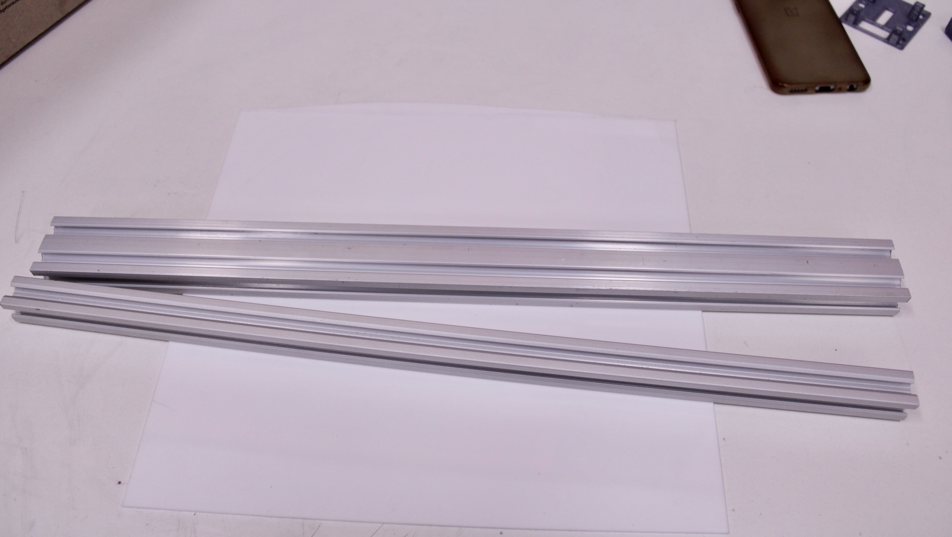
For the frame:
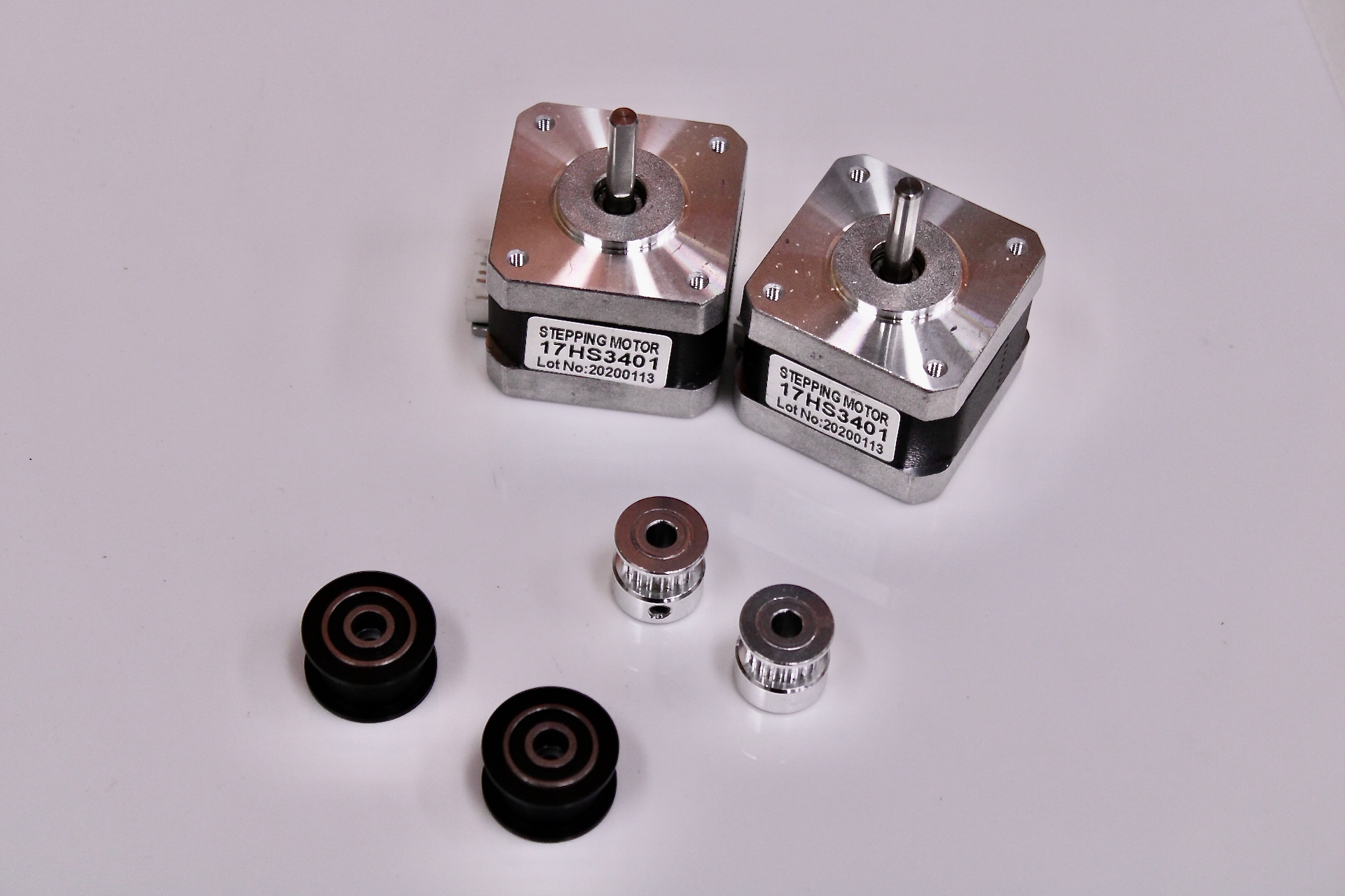
Movement:
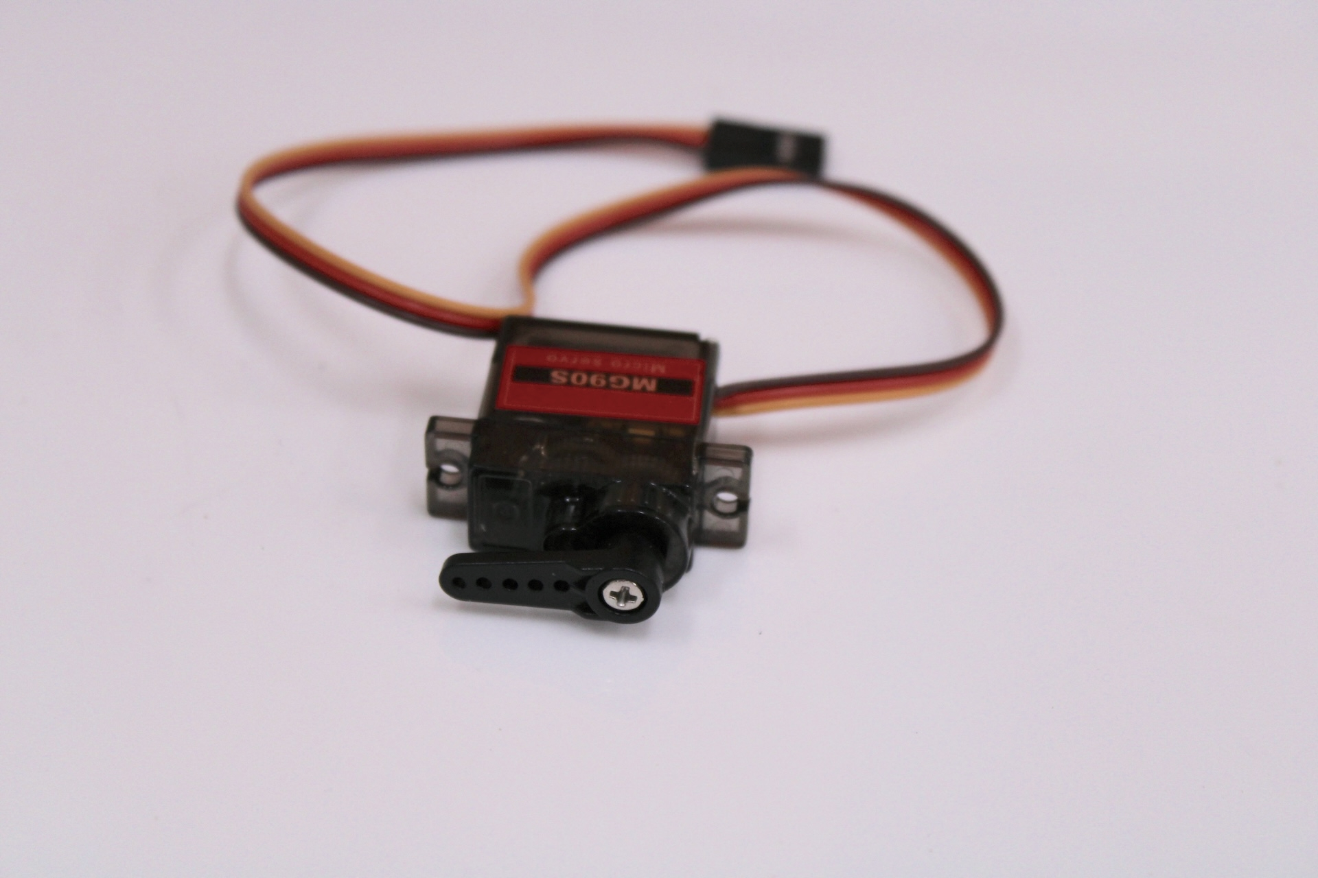
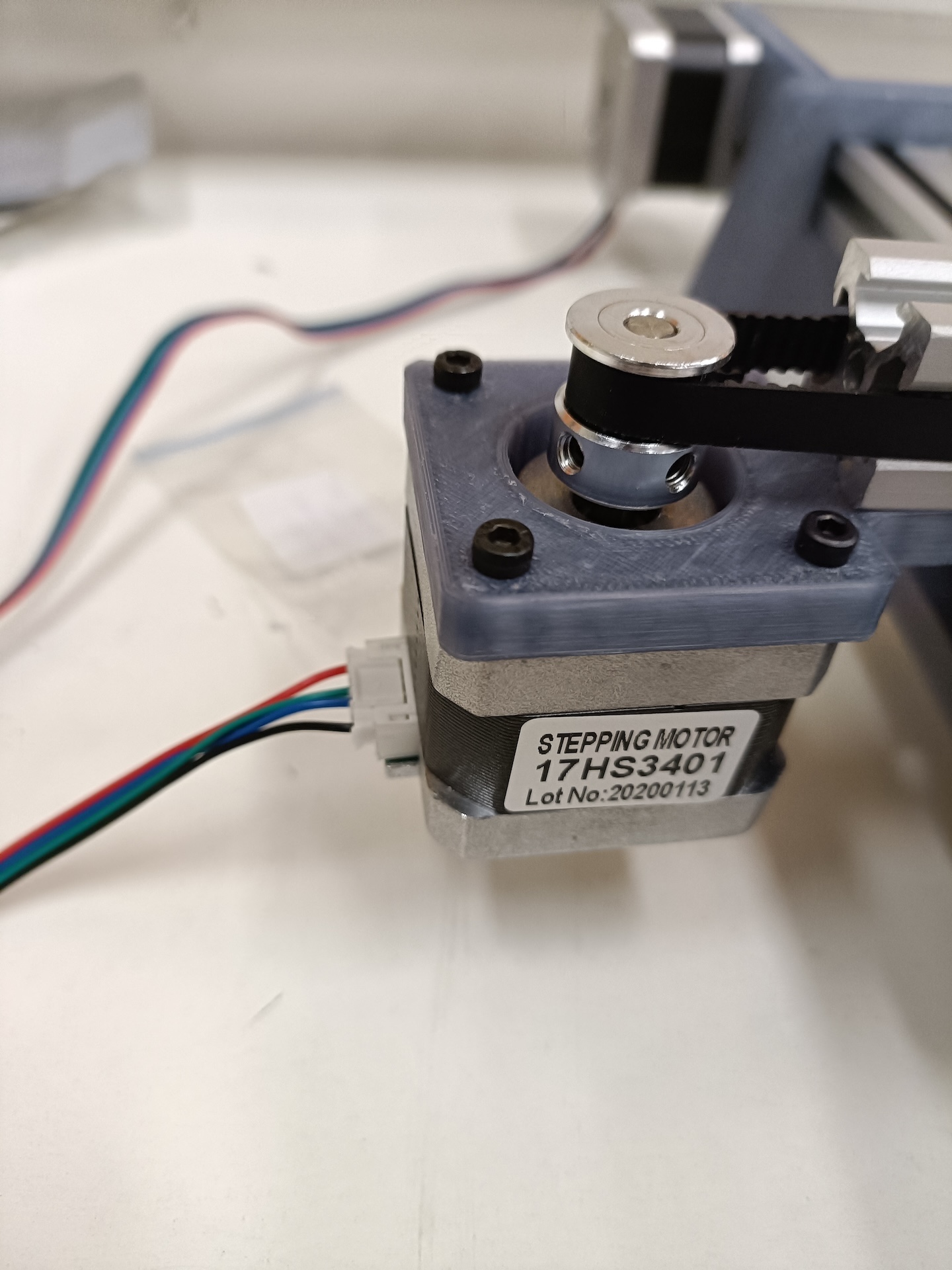
NEMA 17, MG90 Servo, Idler Pulleys, GT2 Pulley (20 teeth)
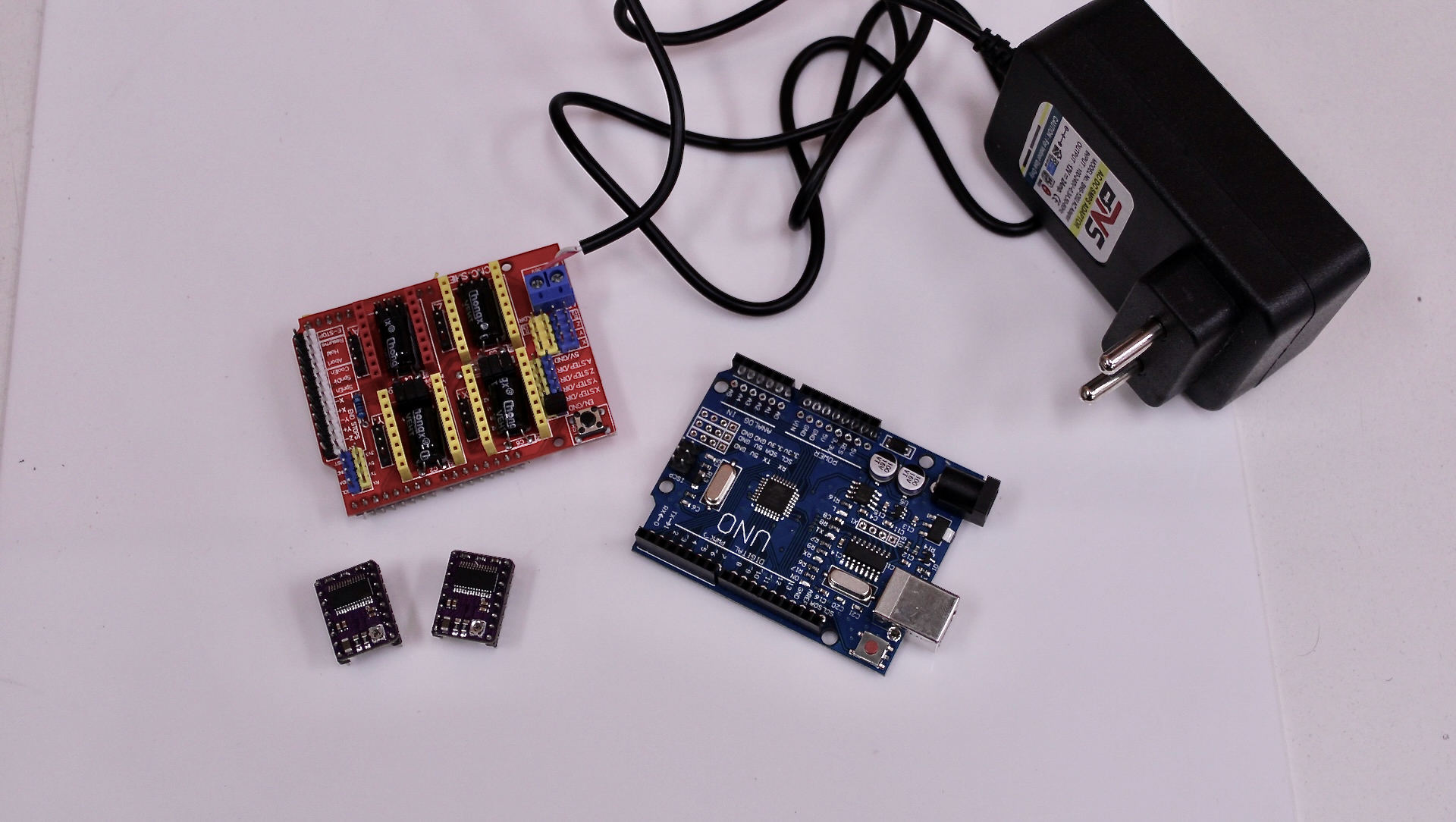
Electronics
Arduino UNO R3, CNC Shield V3.0, DRV8825 / A4988 drivers
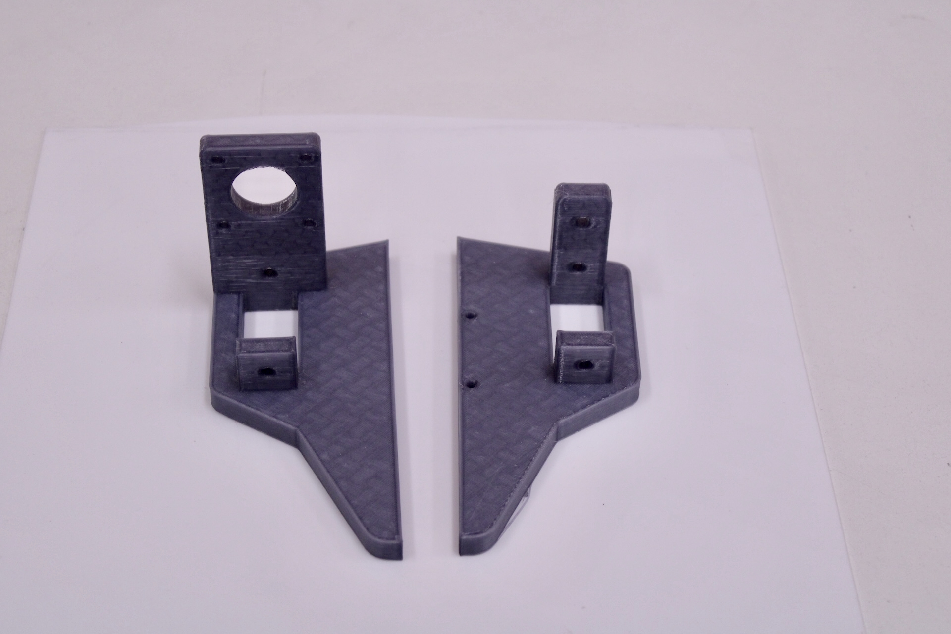
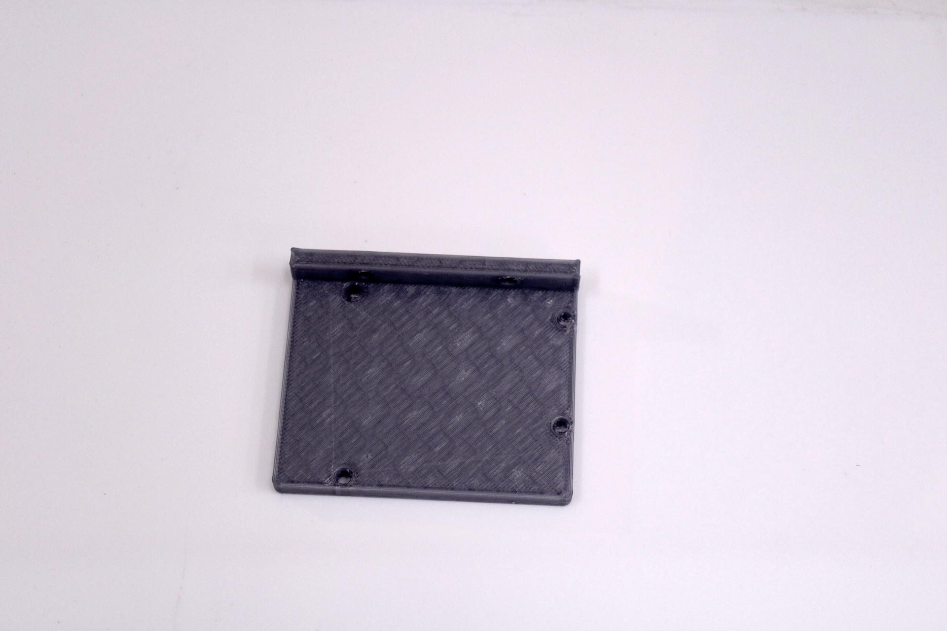
3D Printed Parts
X axis feets + mounts + arduino plate
 X axis wheel plates
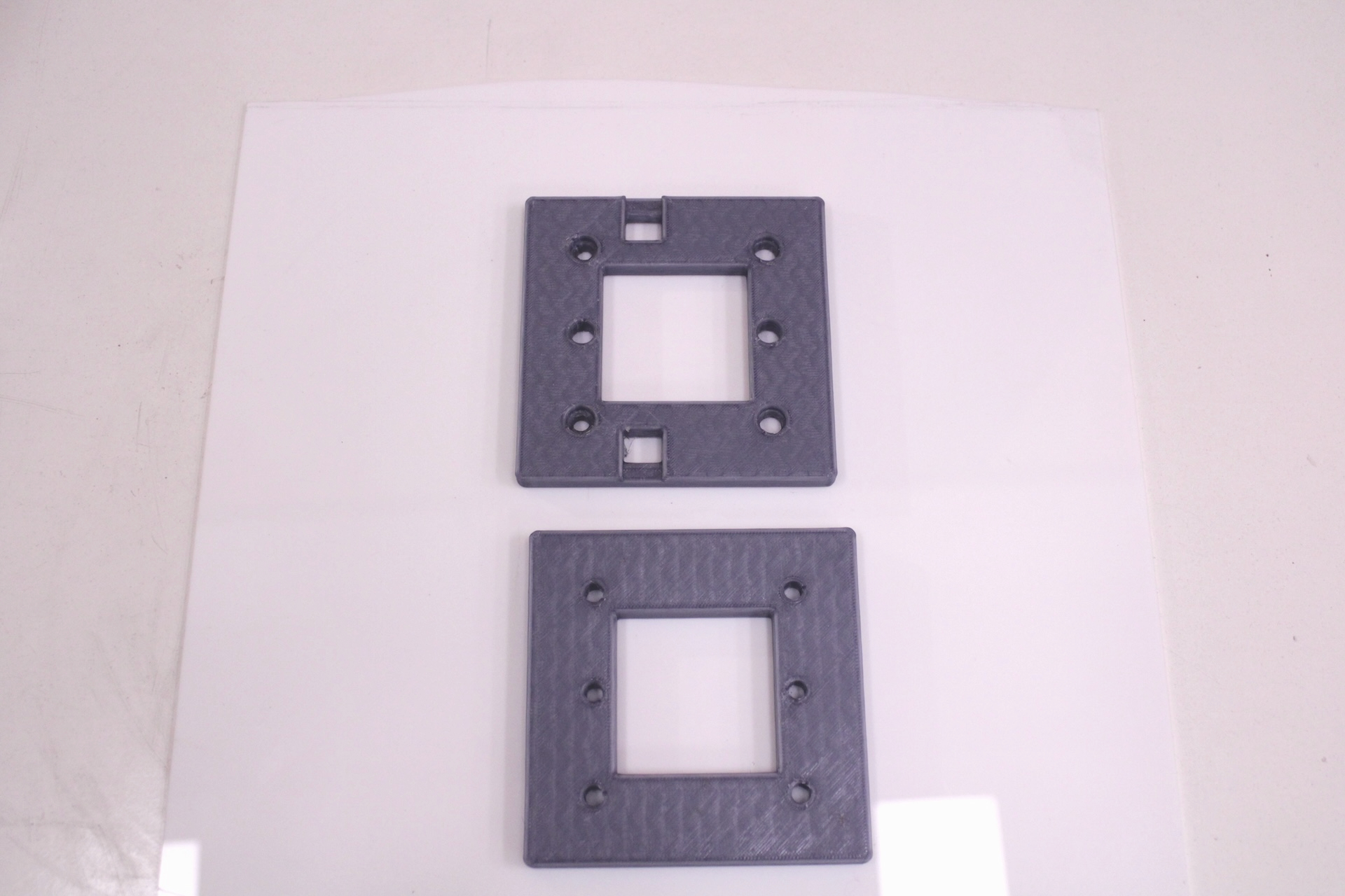 Y axis wheel plate
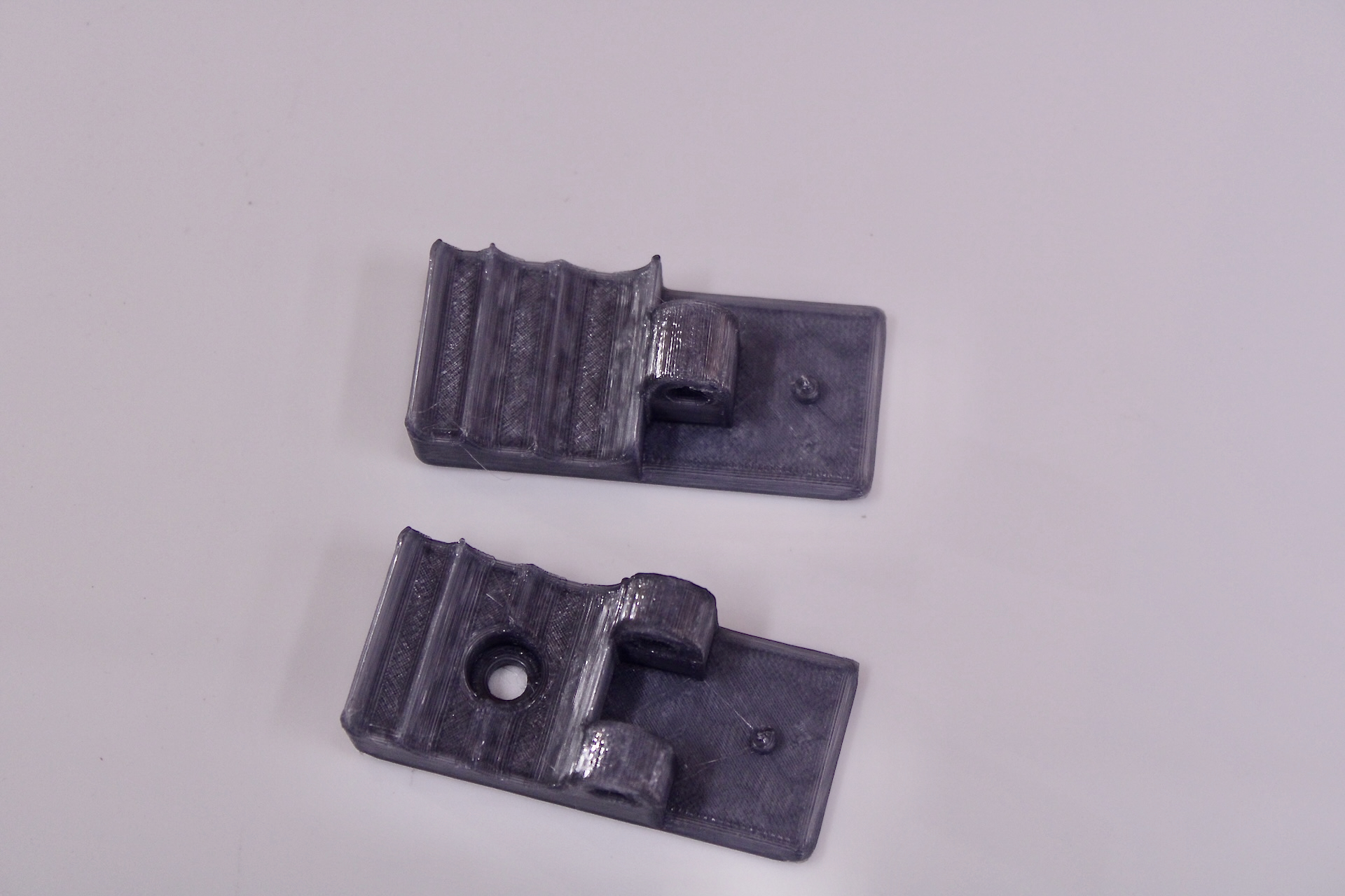
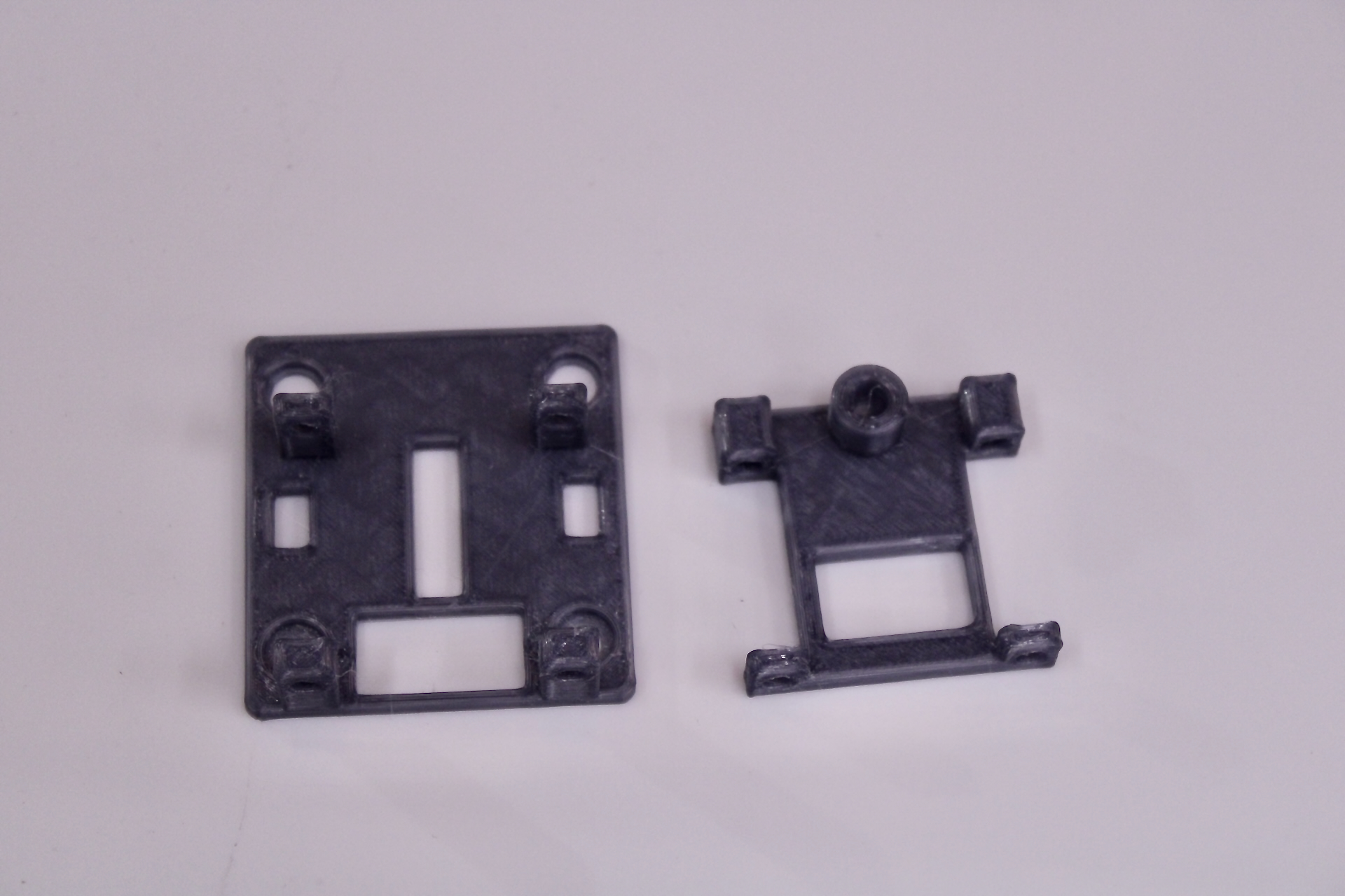 Pen Clip
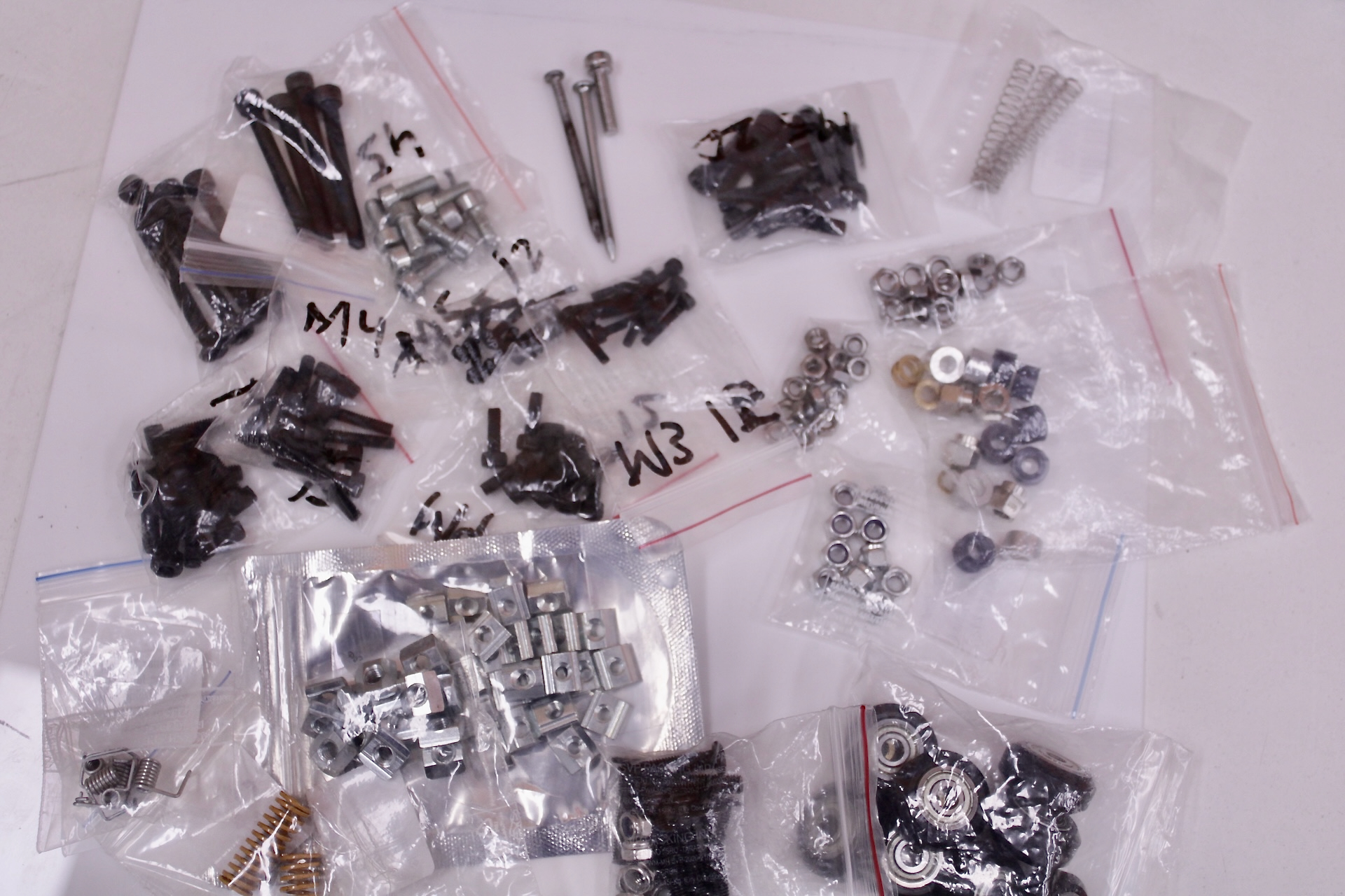
Nuts, Bolts, POM Wheel Kits:
Setting up the electronics
It always nice to ensure that the electronics we just bought aren’t faulty. Here’s how I went about it:
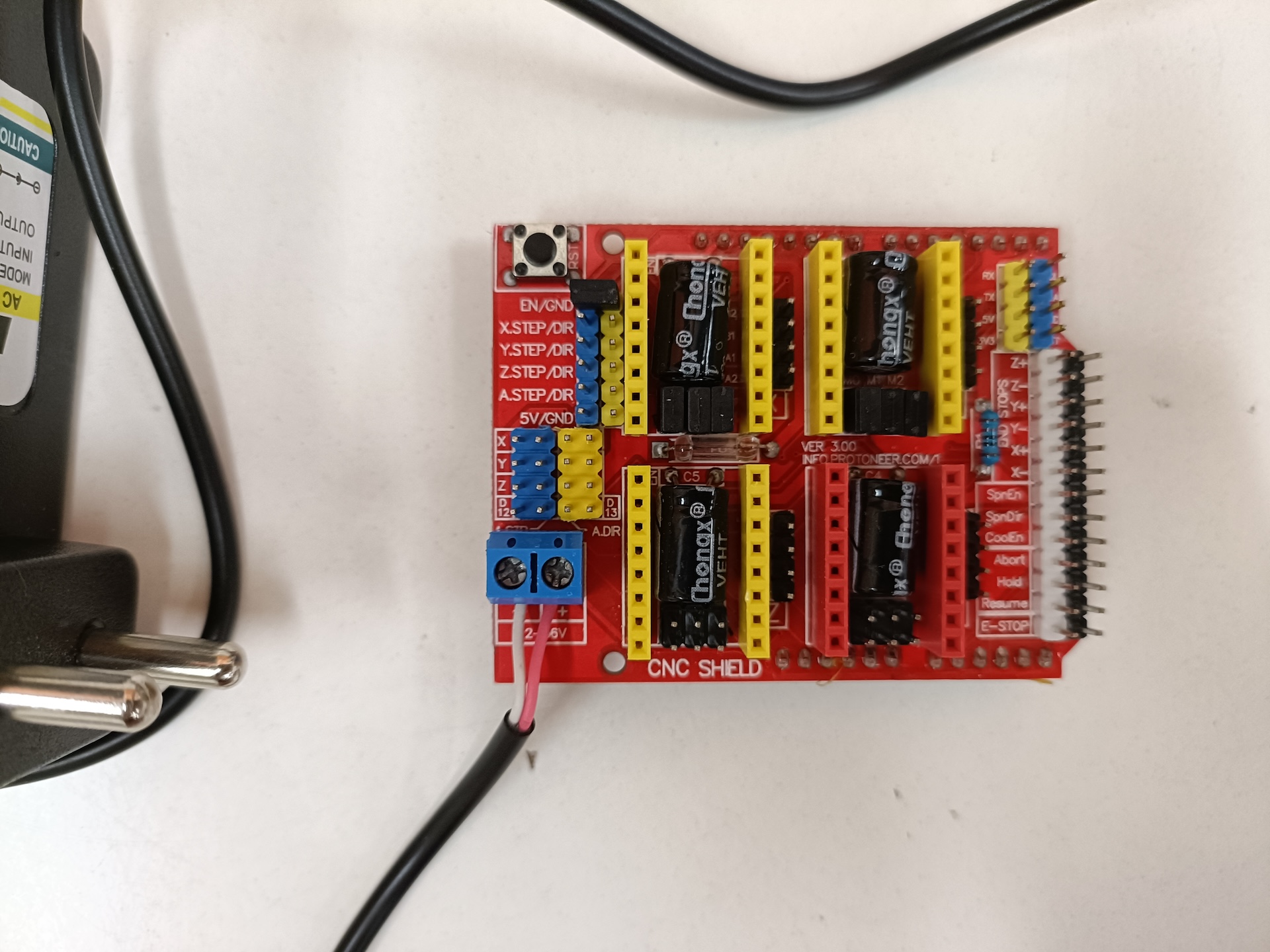
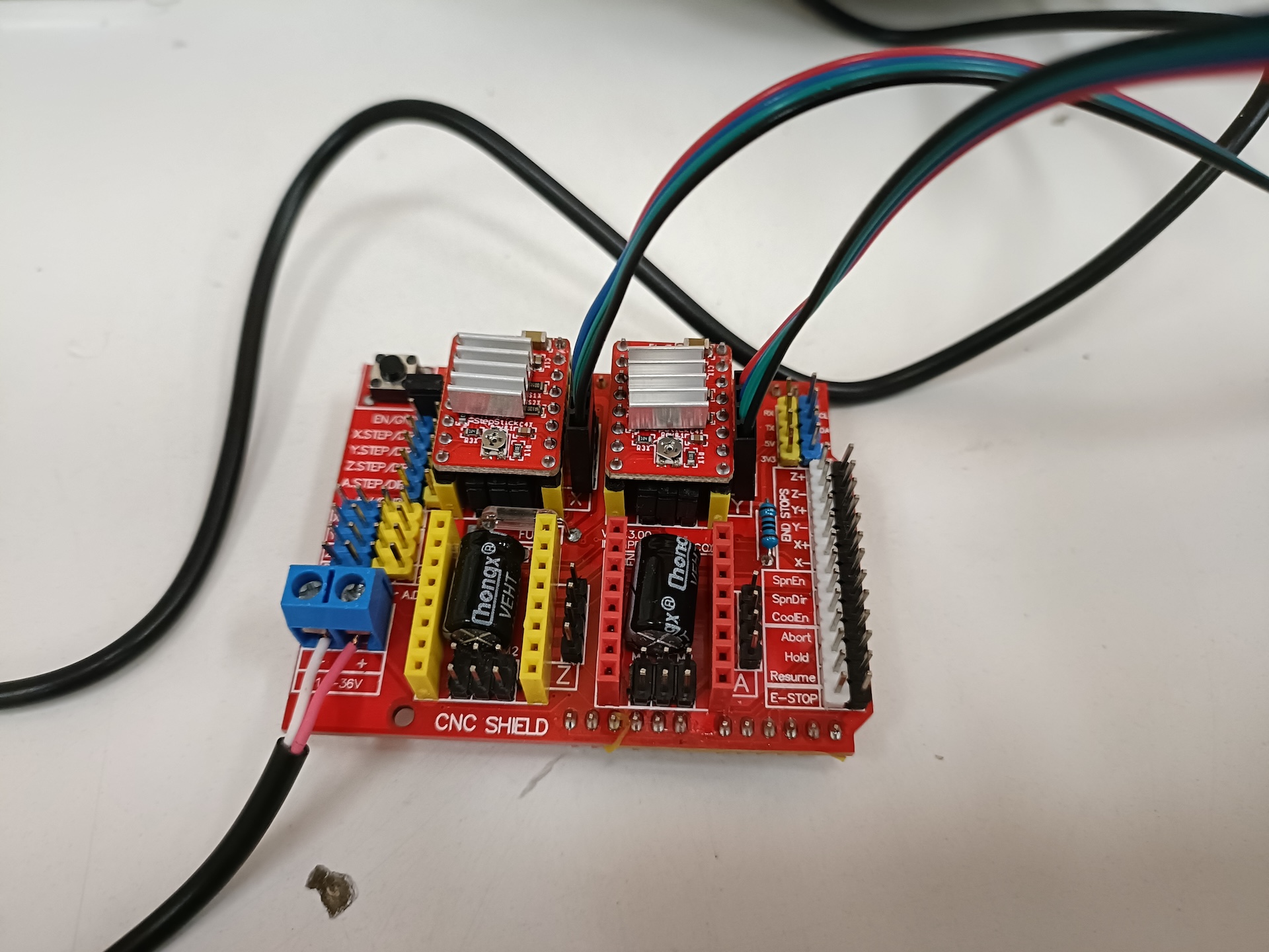
Prepare DC adapter’s connections to the CNC shield
- Cut the DC barrel plug
- Strip roughly 3 cm of the black wire
- Strip the red and white wires
- Use a multimeter to confirm polarity (Red: +, White: -)
- Twist the cables and insert them correctly into the shield’s power supply input.
Refer to photos below.
Alternatively, one can use a ready-made adapter the connector. It should have a female plug for the barrel plug, and two wires (one for + and - each).
Enable CNC shield
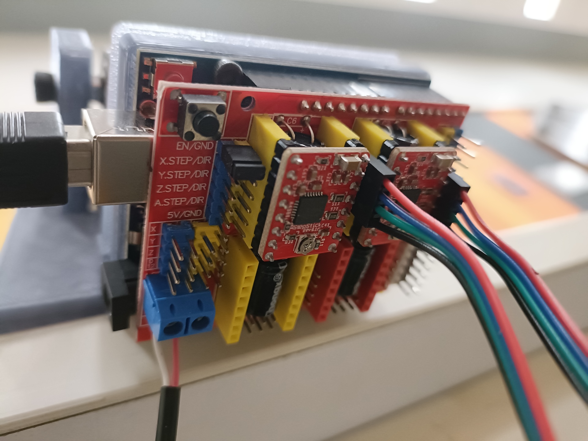
- On the left side of the shield, find the two pins labelled EN and GND.
- Put a short circuit jumper across these. This enables the shield. See photos below.
Setting up the drivers
- Notice the pins below the X and Y axis capacitors, connect all the 3 resolution pins using short circuit jumpers.
- Align EN of the shield and the driver
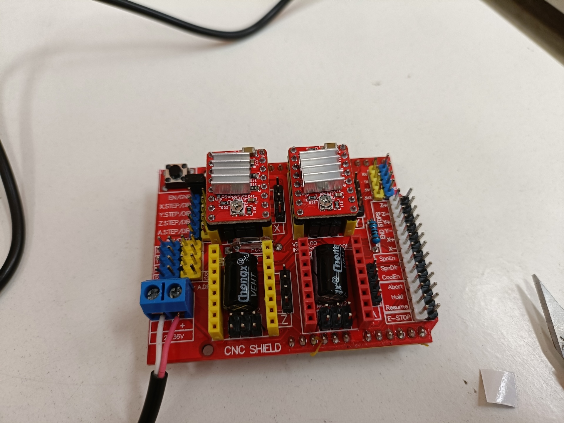
- Attach the stepper drivers to x and y axis slots of the CNC shield.
-
(Temporary) Attach the shield to the arduino.
- Do a test run of the motors and drivers. The test code available on this repo (click here) can be used. I found it on this YouTube video.
- Simply attach the motors to the shield, upload the code to the arduino, power on the DC adapter and the two motors should gently spin with a short pause right after.
- If the motors are too noisy / not spinning properly / heating too much, set Vref according to your motor driver (since the current limit for the steppers is 1A). Consult the internet for details on this step.
Servo
- The cable on the servo is tiny. It must be crimped and extended.
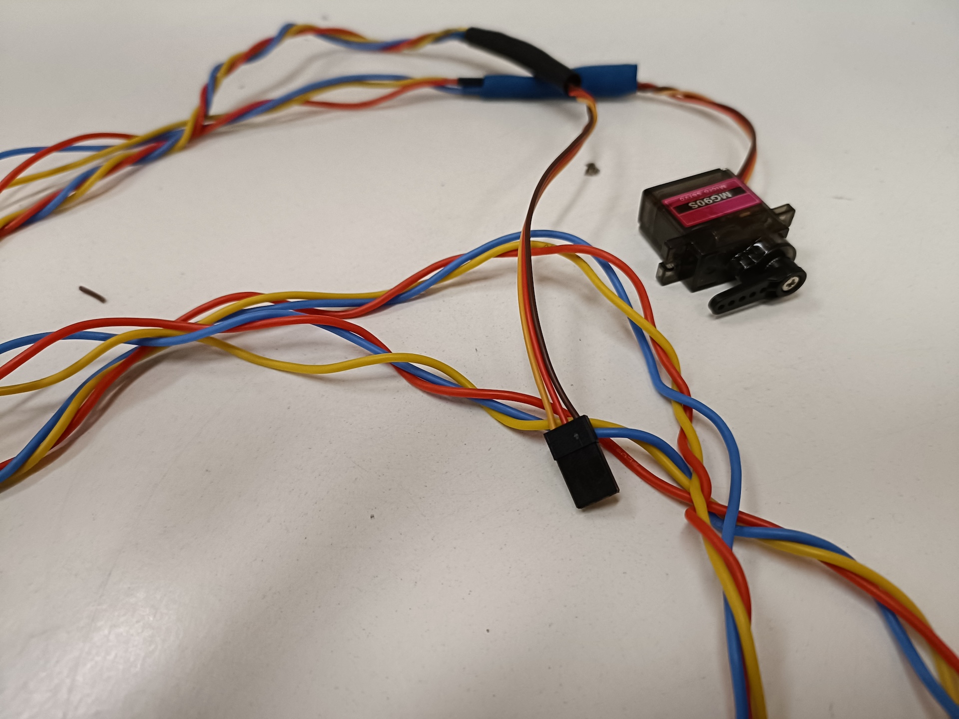
- Use the smallest wing that came with the servo, screw it in.
Assembly
Build instructions
In hindsight, here’s the order I would suggest to someone following this blog as a guide to recreate the build:
2040:
- Attach the feet to the 2040 extrusion: Use M4 sliding nuts to bolt them onto the profile.
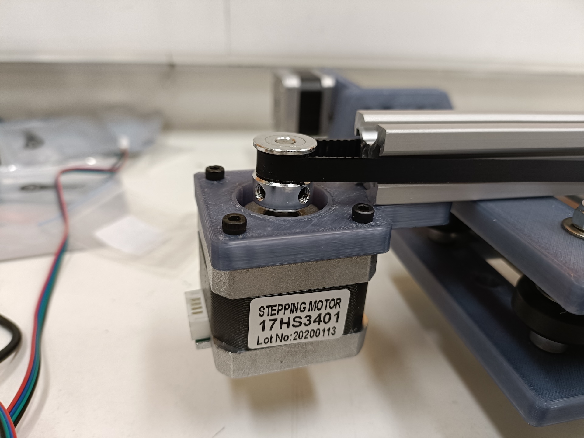
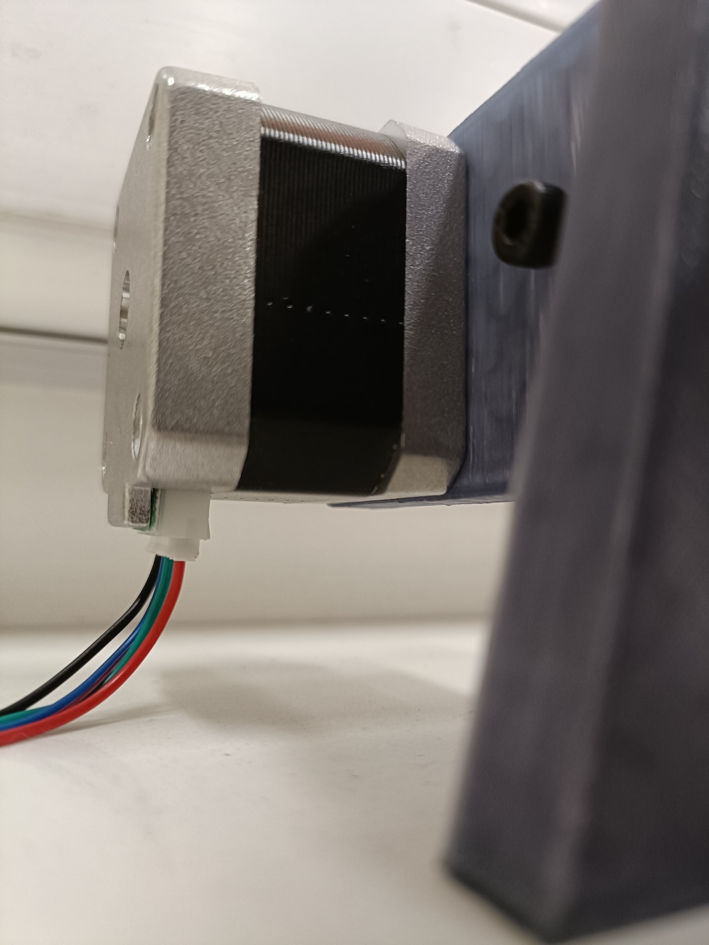
- Bolt on the stepper motor (NEMA 17) to the right side. Install the GT2 pulley on it, aligning it with the profile.
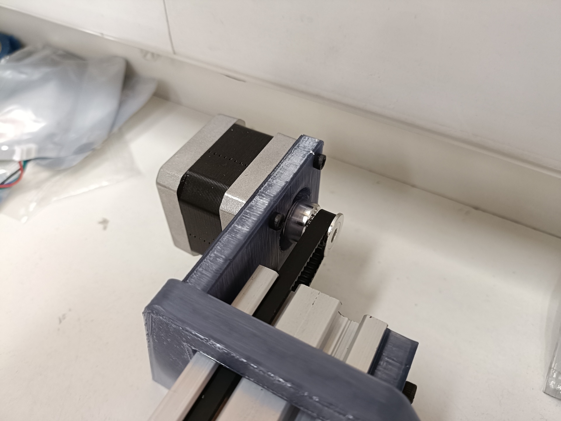
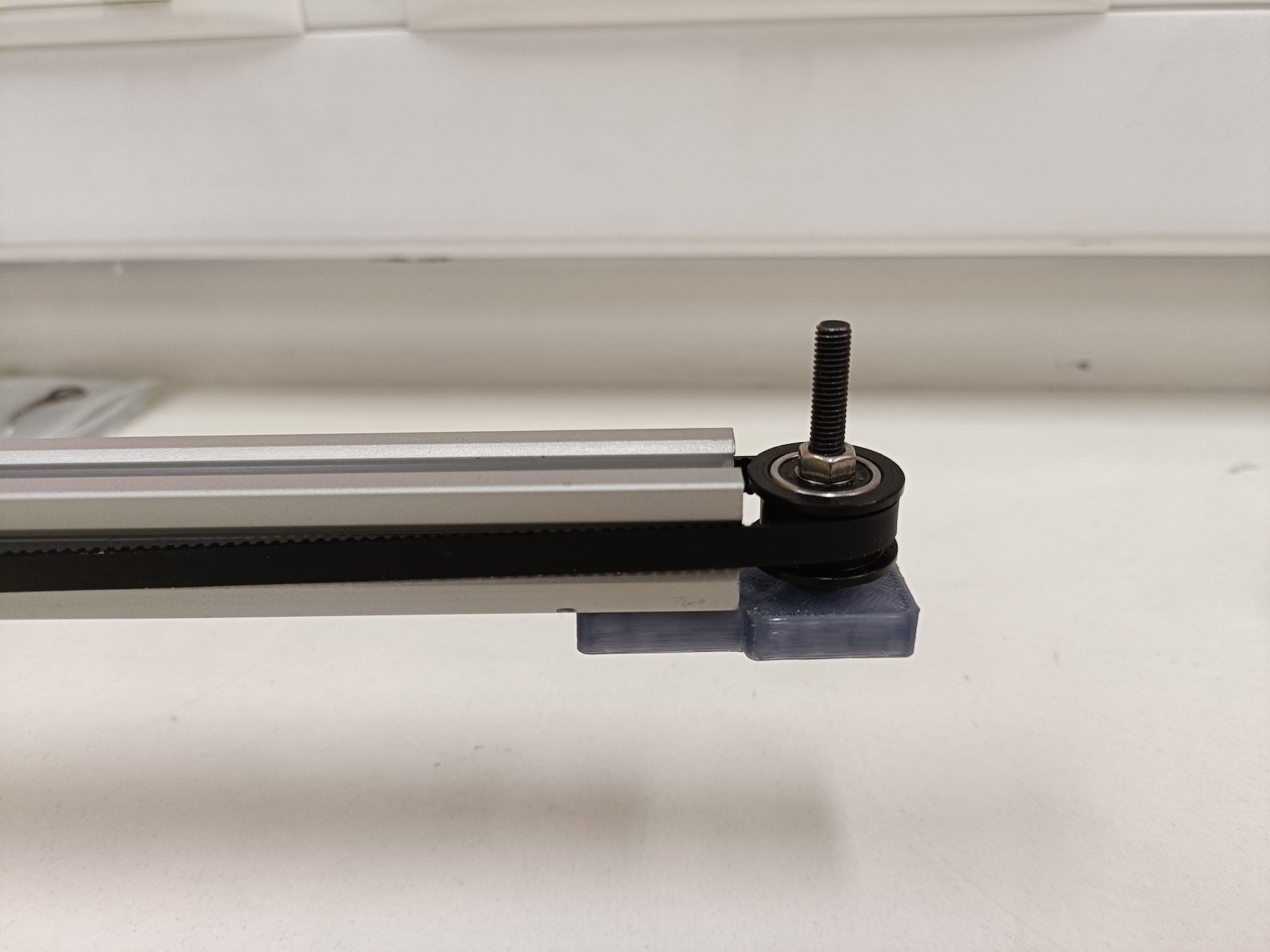
- Bolt on the Idler to the left.
- Attach the top x-gantry plate to the 2020 aluminium profile with M5 bolts and T-nuts.
 Fasten tightly towards one side of the 2020 profile. Leave enough from the edge, we will attach the 2nd stepper motor here later.
 - Insert the M5 45mm bolts in the holes of the x-axis gantry plate. Flip it over so that the bolt heads are on the table-top. Insert the spacers - two normal and two eccentric. Now insert the shim washers and then the wheels. Now insert the extra (round) spacers.
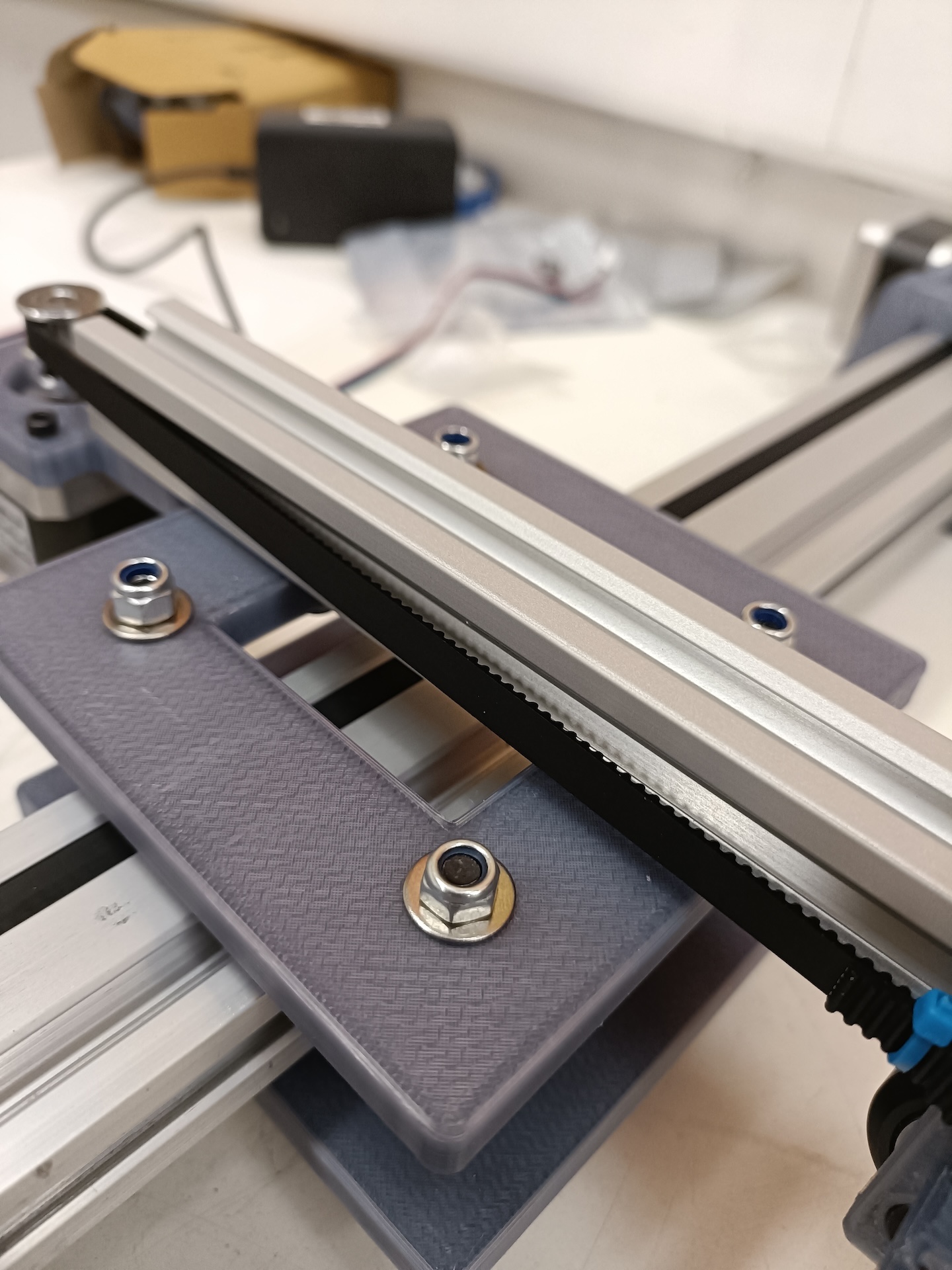
- Once all the parts for the wheels have been inserted onto the bolts, put the wheels & gantry onto the profile. Ensure that the belt cutouts are in line with where the belt will be installed on the pulleys.
 Now attach the other x-axis gantry plate, and use the hex (or nyloc) nuts to complete the x-axis gantry assembly.
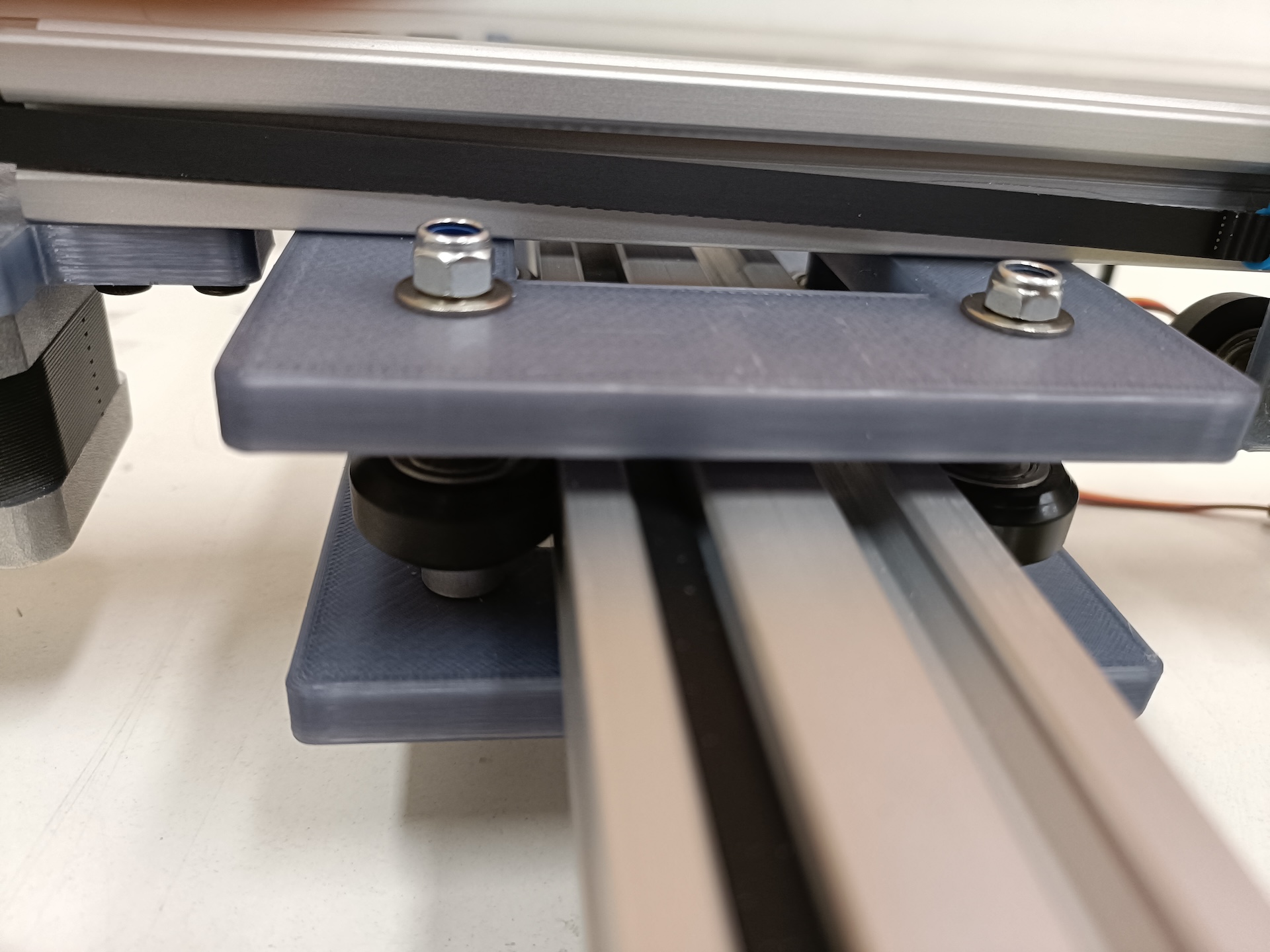
2020:
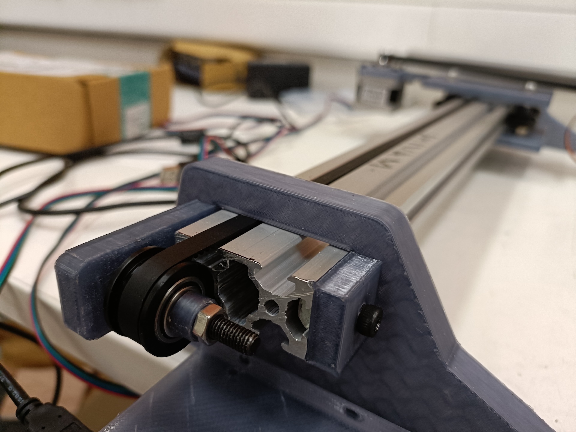
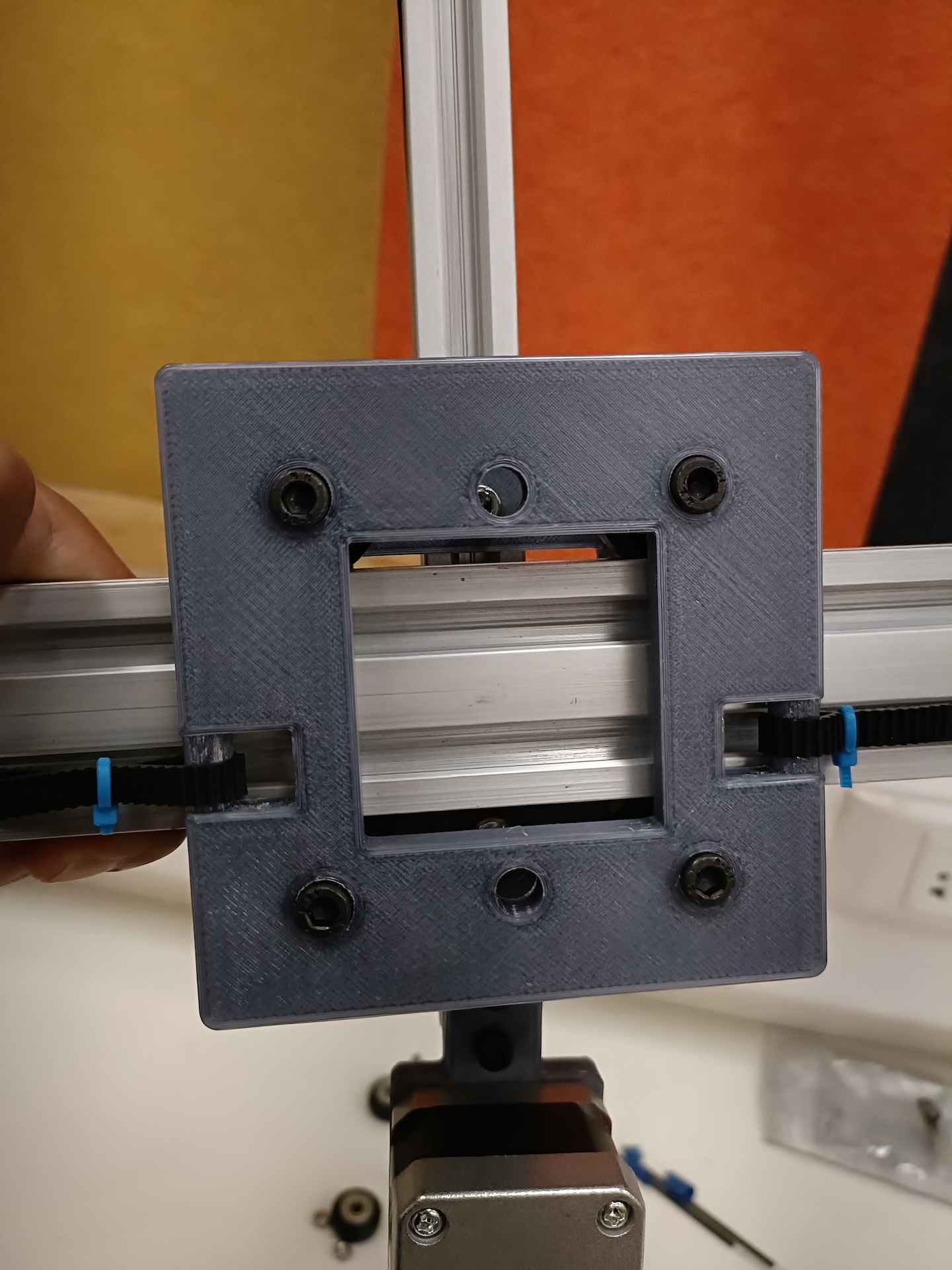
- Similar to the 2040 gantry, attach the wheels onto the y-axis gantry. There is only one gantry plate.
- Now slide the gantry onto the profile.
- Attach the NEMA with the spindle pointing towards the cieling. The idea is to later have the belt running along the front and the back of 2020 profile.
- Attach the GT2 pulley on the NEMA and similarly attach the Idler on the other side.
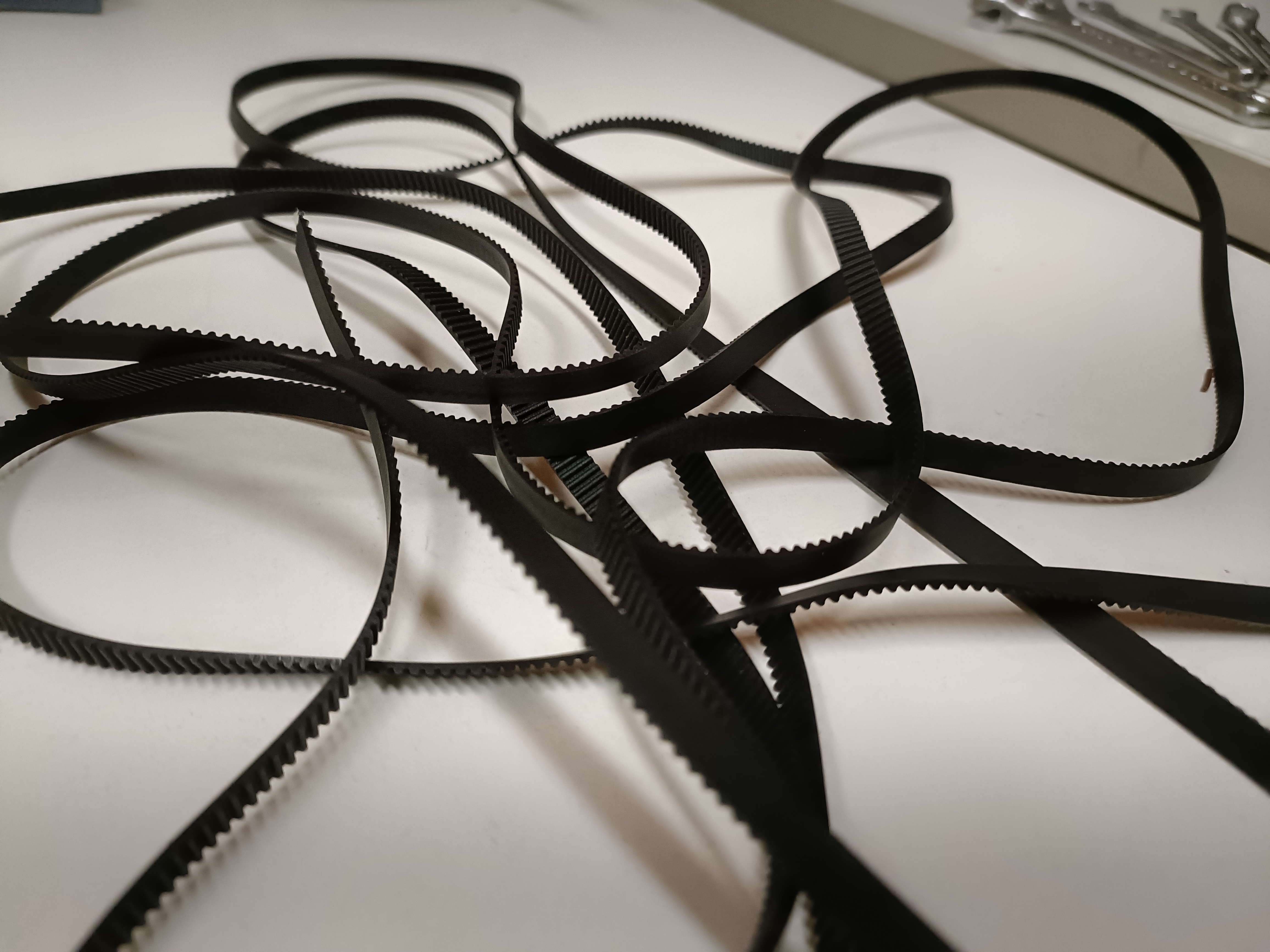
Timing belts: It essential that the belts are have enough tension. This is tricky business. The wheels must slide properly but also not be too loose.
- X-axis:
- start by slightly adjusting the feet and pushing them inward by a couple mm on either side.
- slide the belt into one the cutouts of the gantry plate, all the way around the 2040 profile, the NEMA 17 followed by the other and slide it out of the other cutout. If you haven’t cut the belt to an appropriate length yet, ensure you leave 3-4cm excess on both ends before cutting.
- Loop the belt around the cutout, pull the belt taut, it should be come tight and sit flush on the pulley teeth. Now use mini-zipties to fix that end of the loop.
- Repeat on the other cutout. Ensure the belt it tight once it has been looped and ziptied around both sides of the gantry.
- The belt tension can be adjusted slightly by sliding the feet inward or outward.
- Y-axis:
- Repeat the above process: loosen and slide the mounts of the motor & idler inwards, loop the belt in and around the belt cutout on the gantry and then ziptie it. Same for the other end. Once done, slide the motor & idler mounts outward to ensure enough tension on the belt.
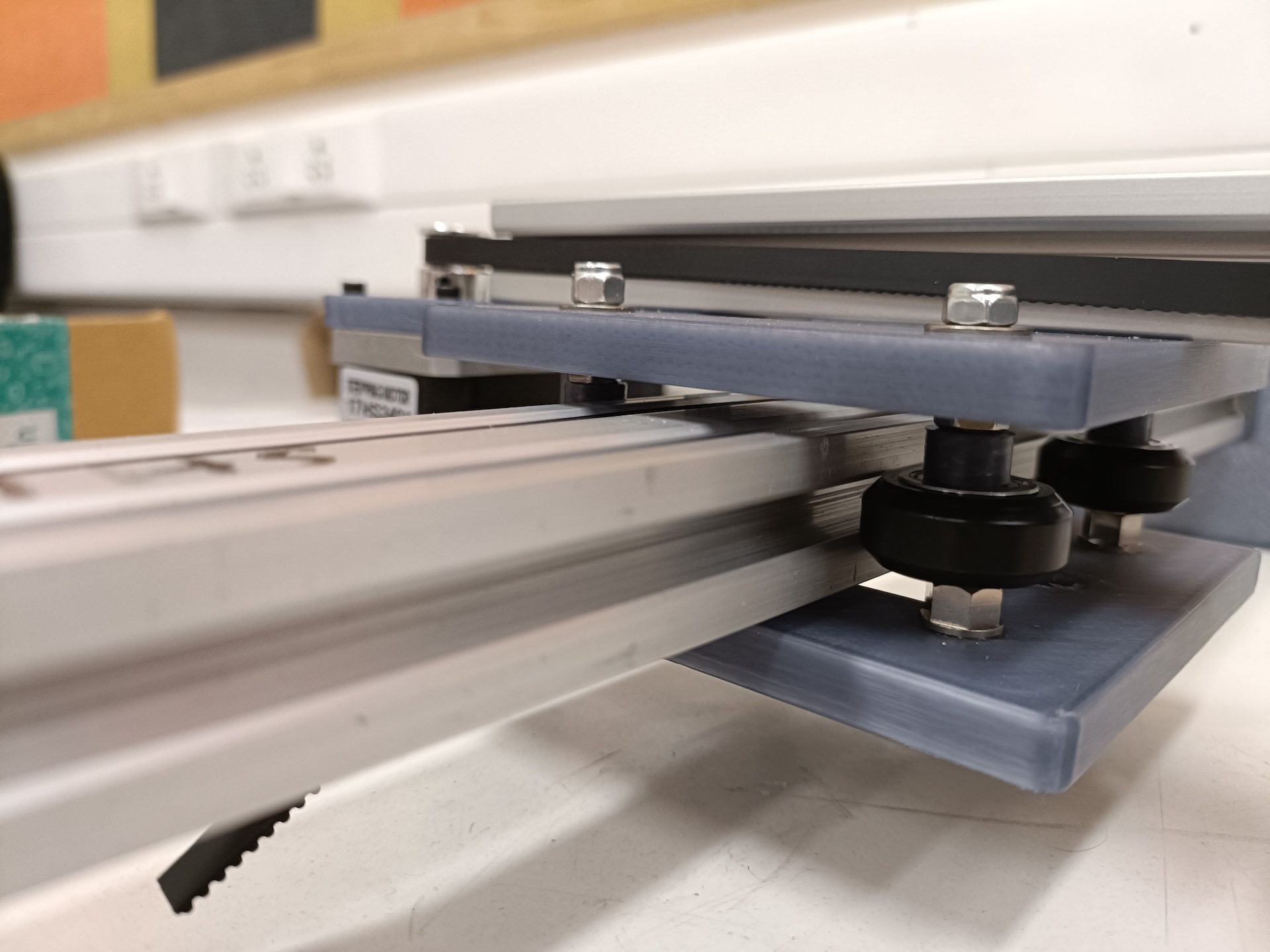
- Tune the wheels. Here are some tips:
- Wheels can be tuned by turning the eccentric spacers using an appropriate wrench.
- The gantries should slide smoothly under gravity.
- When the gantries mvoe, all the wheels should turn. At the same time, if you turn one of them by hand, it should turn easily and not feel stuck.
Pen Clip:
- First, use an M5 bolt to the attach the fixed end of the clip to the pen lifter. Use a 5mm hex nut to fasten the bolt.
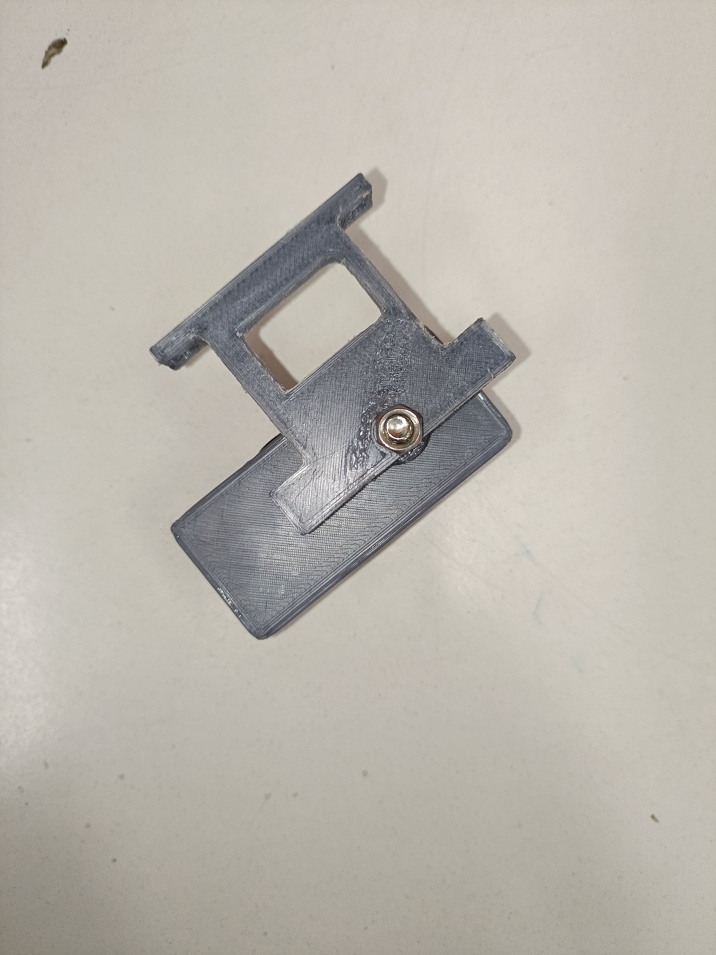
- Next, fit the 3D printer spring on the circular plastic extrusions on the two halves of the clip.
- Insert an M5 bolt while aligning the holes of the two halves to join and complete the clip.
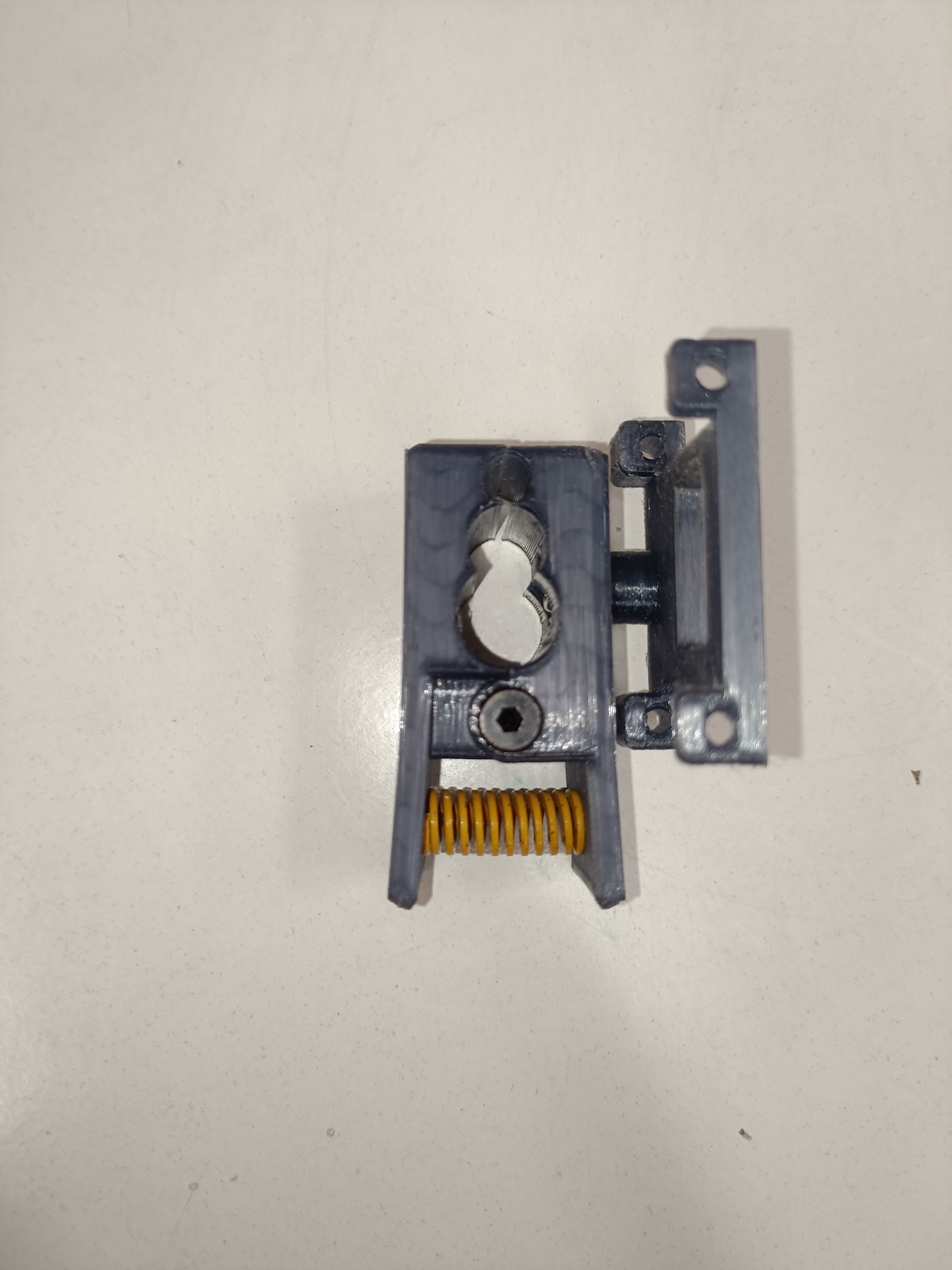
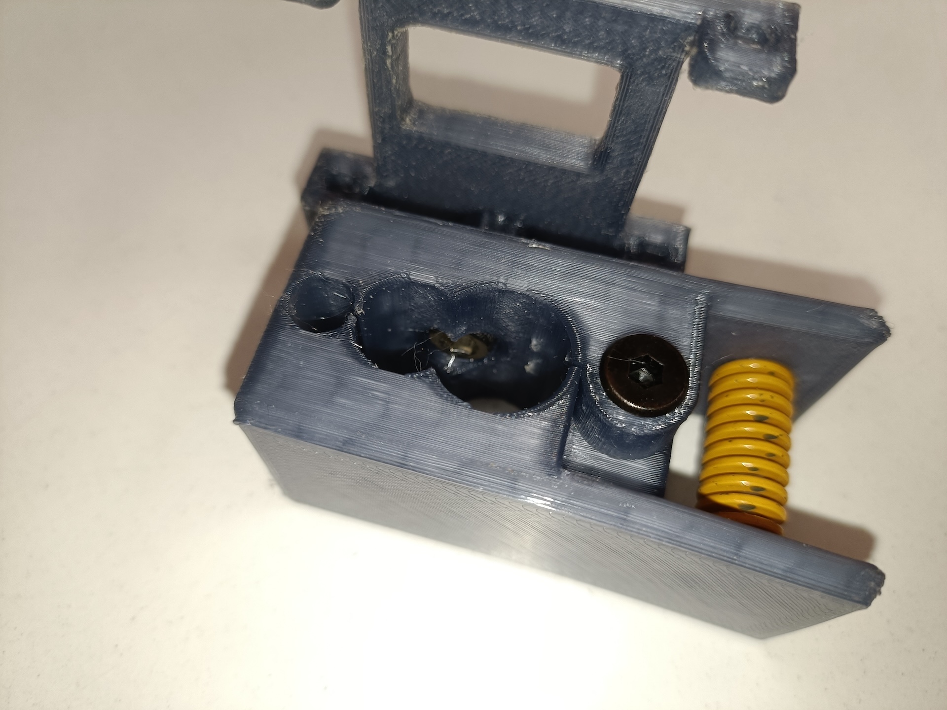
Pen Lifter:
- Attach the servo to the y-axis gantry plate. Use the tiny screws to fix it in place.
- Align the springs with the holes of the pen lifter.
- Align the holes of the pen liter and the gantry plate. Now insert the refill / 3mm rods on both sides. It shouldn’t take too much force to compress the springs.
Arduino Plate:
- Attach the arduino plate to the left foot (of the 2040 gantry). Use M3 (>= 20mm) bolts and 3mm hex nuts.
- Align the arduino holes and bolt the board onto on the plate. Fasten using hex nuts.
Wiring & Electricals
- Ensure that your electronics work. Setup the stepper drivers as mentioned earlier.
- Connect the motor on the 2040 profile to the pins of the x-axis stepper driver on the CNC shield. Use a long cable.
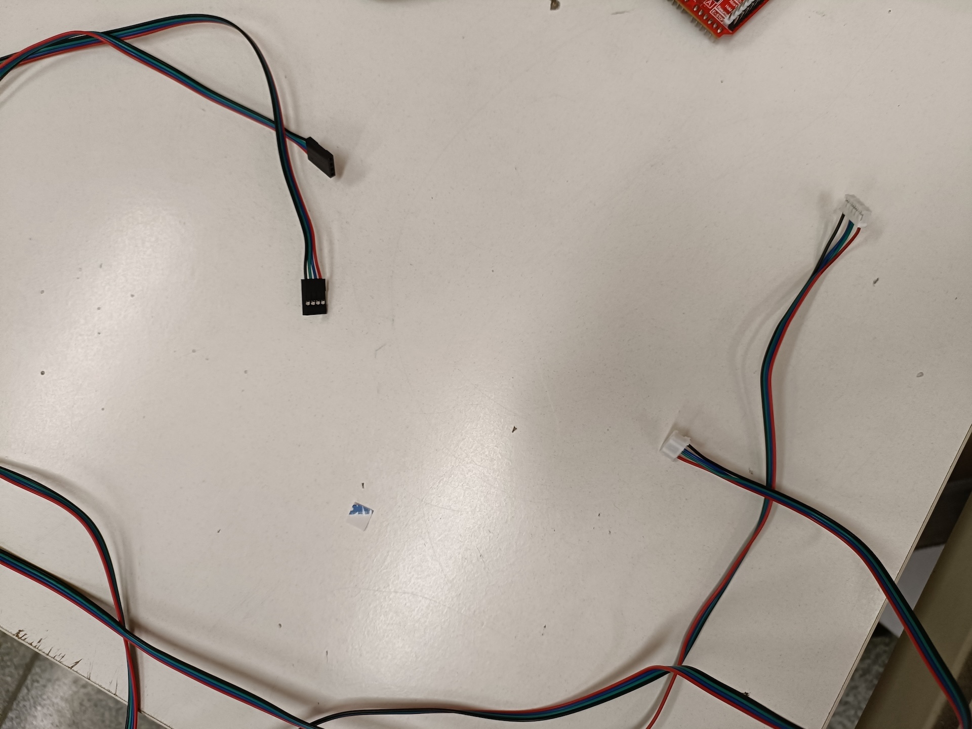
- Connect the motor on the 2020 profile to the pins beside the y-axis stepper driver.
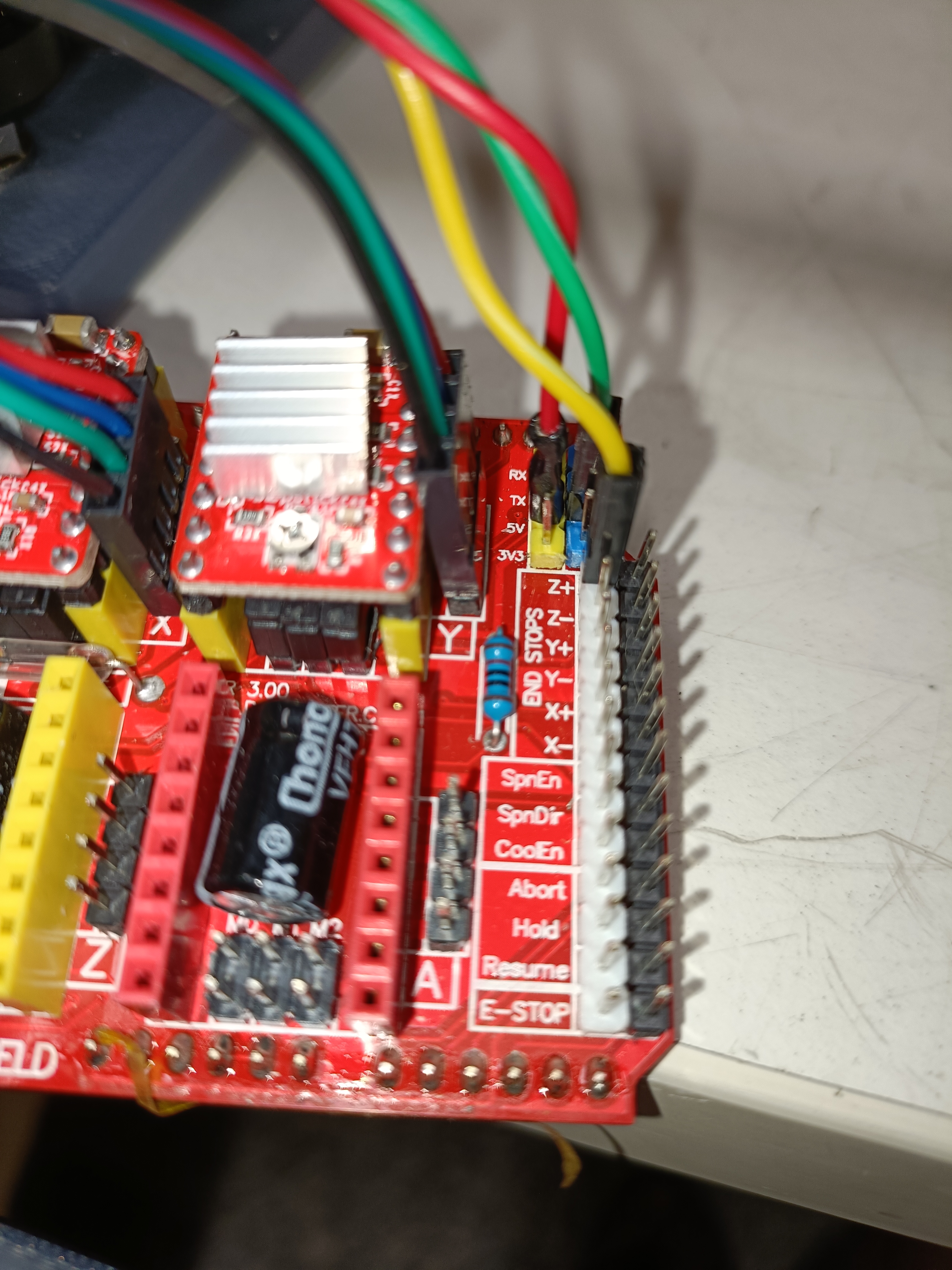
- Connect the servo to the pins as shown in the image. (The red & yellow wires correspond to the servo’s red & yellow, the green extends the servo’s brown.)
- Connect the CNC shield to the arduino. The cutouts of the boards should be aligned.
- (Optional) Use a housing for the cables.
Adding the Code
-
Connect computer to the arudino using a USB cable.
- Compile and upload GRBL (modified for servo) to the arduino.
- GRBL for servo: https://github.com/bdring/Grbl_Pen_Servo
- Compilation Instructions: https://github.com/gnea/grbl/wiki/Compiling-Grbl
- Install a G-code sender. I used UGS (Universal G-Code Sender): https://universalgcodesender.com
Read more about G-Code here: https://www.norwegiancreations.com/2015/08/an-intro-to-g-code-and-how-to-generate-it-using-inkscape/
Example Usage
-
The wall adapter powers on the stepper motors. Make sure to move the X and Y axis to where you would like the X0 and Y0 coordinates to be before switching on the wall adapter.
-
Connecting the arduino to your laptop using a USB cable powers up the servo.
-
Generate the G-Code files using suitable software. (I had trouble finding plugins that would be compatible with my laptop, so for the test run, I used a random G-Code file available on the internet.)
-
Open your G-Code sender app. Connect to the machine.
-
Adjust the machine’s firmware settings, the setup wizard on UGS can help with this.
-
While using UGS if there is an error claiming the feed rate wasn’t set, enter
F<some-feed-rate>(e.g F1000) in the console. -
Select and send the G-Code file using the sender.
Thanks for reading, hope this inspires you to build something on your own!